DPART Sample Testing Report 7.30.20
Report: 3-point bending mechanical testing
Mechanical testing was prescribed to two carbon fiber reinforced epoxy laminates made with the traditional VARTM infusion process and a new Instaclave DPART process. Mechanical testing of the specimens will illustrate two significant properties. First, a method and procedure to compare two different manufacturing processes for the same material system, and second, performance of the new manufacturing process under representative loading conditions in industry operation.
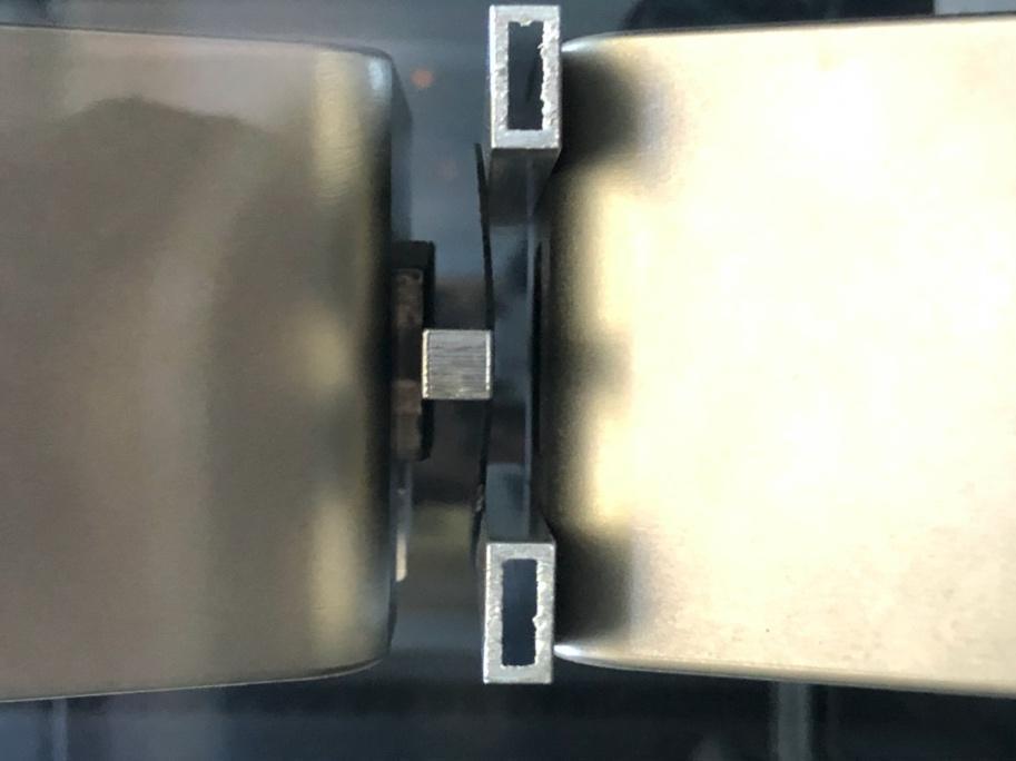
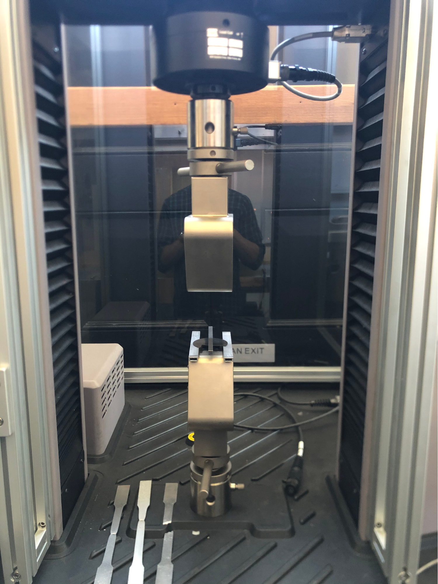
3-point bending flexural tests were chosen instead of traditional tensile tests. In this instance, tensile tests would not give adequate information on the performance of the Instaclave manufacturing process over the traditional VARTM infusion process. The Instaclave process freezes the laminate fibers in tension, and tension tests would show just that, the composite failure under a perceived lower yield point, since the material has already traversed a portion of the elastic linear region in stress-strain space. Tensile tests would also not elucidate a key feature of the Instaclave manufacturing process; the enhanced performance of transverse or structural loading. 3-point bending flexural tests load the composite in the transverse direction and can produce results consistent with structural loading. 3-point bending flexural tests were performed over 4-point bending flexural tests due to specimen size constraints, but, as is prolifically documented, produces the same mechanical property information. Figure 1 is an image of the MTS mechanical testing platform and the 3-point bending flexural test assembly.
3-point bending flexural tests were performed using an MTS 43 test system with a 50 kN maximum load. Steel bars (details to be added) were used as simple supports and bending anvil. The specimens, of equal dimensions (details to be added) were oriented with one ply perpendicular to the simple supports, and dimensions/spacing were recorded for analysis (details to be added). The samples were loaded with 0.01 mm/sec displacement conditions until sufficient material failure was observed. The output of the test system included loading force, crosshead displacement, and testing time. These parameters were used, along with dimensional values, to calculate various mechanical properties so as to compare the two specimens' ultimate performance.
The metrics of interest are bending and flexural stress, flexural strain and flexural modulus. Bending and flexural stress represent similar quantities, while they both are rooted in Bernoulli-Euler beam theory, their exact derivation and calculation results in separate quantities (details to be added). Correlation of the two is expected and discussed. Flexural strain represents the strain experienced from material displacement and is an extension of the classical expectation of strain, but takes into account the curvature due to loading (details to be added). Flexural modulus (also known as the Bend modulus) is a measure of a material's stiffness and resistance to bend when a force is applied perpendicular to the long edge of a sample. Ideally, the Tensile and Flexural modulus would be the same since by definition they are both the materials' ability to resist deformation under loads, even though the loads they are resisting are different. In short, the material stress will represent a comparative performance metric of the part due to loading, the flexural strain and modulus will enable discussion rigidity of the part.
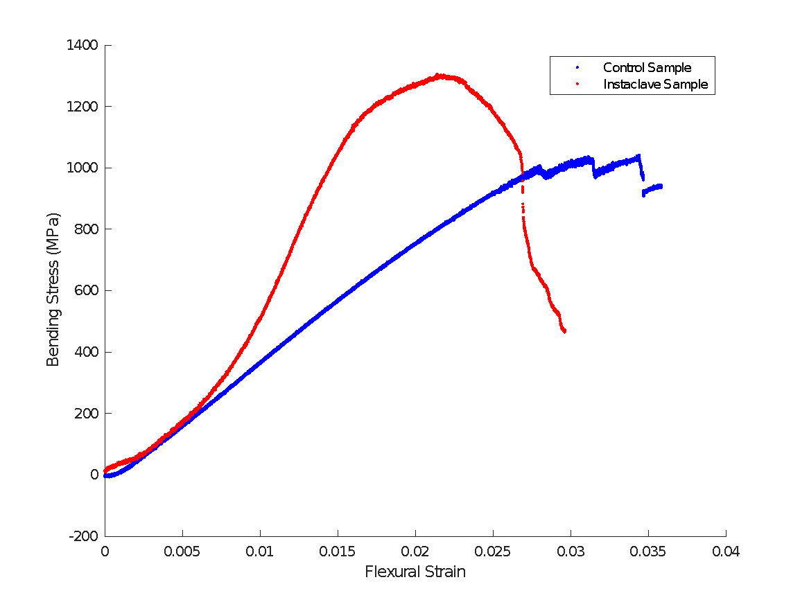
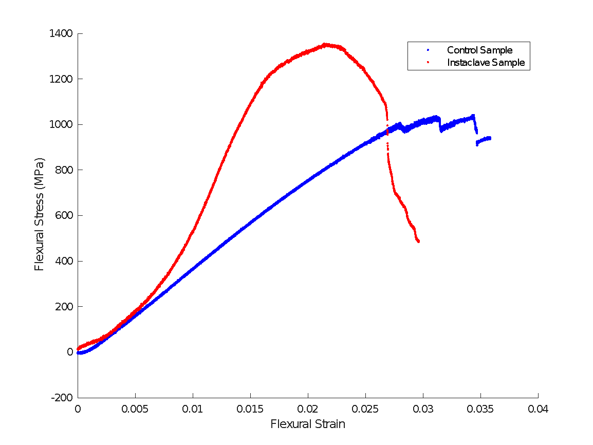
Figure 2 shows bending stress vs flexural strain for both VARTM and Instaclave samples. The VARTM (control) sample shows traditional behavior of a composite specimen, with a long linear elastic region and a fracture region. The characteristic sawtooth pattern indicates ply failure and subsequent reduction load bearing ability by the specimen. After enough plys fail, the stress will drop to a point where it is no longer possible to show significant increase in stress and catastrophic failure is imminent. The Instaclave sample has a non-linear elastic region. This is not an unobserved phenomena, but could be explored further. The bending stress rises sharply above the VARTM sample yet failing at a lower flexural strain value. This early failure could be due to a number of geometrical or manufacturing considerations. The peak point of the bending stress curve is the ultimate bending stress. The ultimate bending stress for the Instaclave sample is 1300 MPa compared to 1042 MPa for the VARTM control sample, or a 25% increase in ultimate bending stress. Figure 3 shows the Flexural stress for both samples, with curves nearly identical to Figure 2, just slightly different values . The maximum flexural stress for the Instaclave part is 1355 MPa compared to the VARTM control part of 1042 MPa, or a 30% increase in ultimate flexural stress.
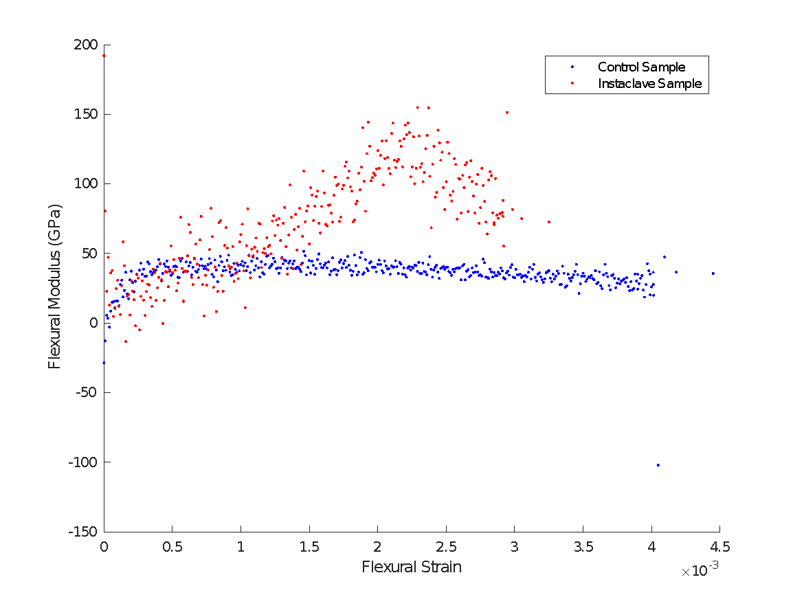
Figure 4 shows the Flexural modulus over the elastic region of the sample loadings. The VARTM control sample shows relatively uniform flexural modulus of about 40 GPa while the Instaclave sample varies from 40 to 150 GPa. Again this variability may come from dimensional or process related variables, and is apparent from figures 2,3 elastic regions.
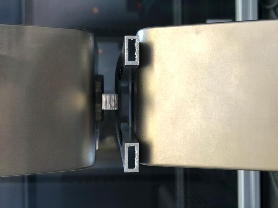
Figures 5 and 6 are images of the 3-point bending flexural tests for both samples.
Figure 1: MTS 43 test system
Figure 2: Bending Stress vs Flexural Strain
Figure 3: Flexural Stress vs Flexural Strain
Figure 4: Flexural Modulus
Figure 5: Control sample in loading
Figure6: Instaclave sample in loading.